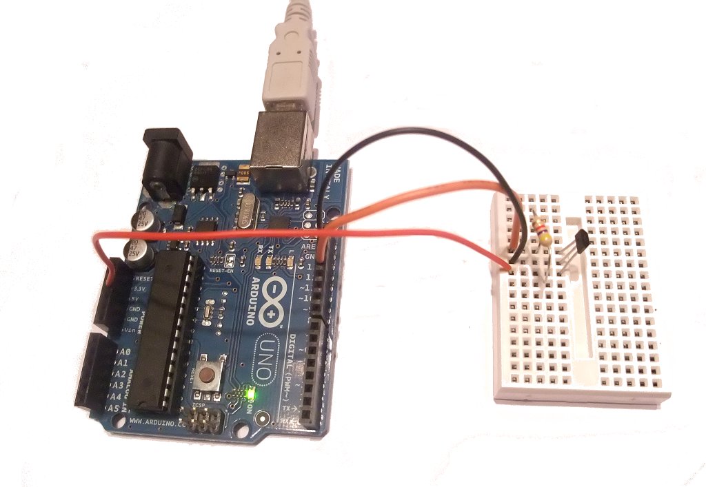
Ok, this is an easy one to make. We are going to use a hall effect switch to turn the Arduino UNO’s built-in led on and off with a magnet.
We will be using the Allegro Microsystems A1120EUA Hall Effect Switch
- Connect pin 1 of the switch to the Arduino +5V supply (red wire)
- Connect pin 2 to 0V (black wire)
- Connect pin 3 to Arduino input pin 12 (orange wire)
A pull-up resistor is required between pin 1 and pin 3 to pull-up the switch’s output to +5V.
When the switch detects a magnet, it will pull it’s output pin low, which we can easily detect on the Arduino board.
Here is the Arduino sketch
/*
 Hall Effect Switch

 Turns on and off a light emitting diode(LED) connected to digital
 pin 13, when Hall Effect Sensor attached to pin 2 is triggered by a magnet

 Hall effect sensor used is the A1120EUA from Allegro Microsystems

 This example code is in the public domain.

 http://www.hobbytronics.co.uk/arduino-tutorial8-hall-effect
*/

// constants won't change. They're used here to set pin numbers:
const int hallPin = 12;     // the number of the hall effect sensor pin
const int ledPin =  13;     // the number of the LED pin
// variables will change:
int hallState = 0;          // variable for reading the hall sensor status

void setup() {
  // initialize the LED pin as an output:
  pinMode(ledPin, OUTPUT);
  // initialize the hall effect sensor pin as an input:
  pinMode(hallPin, INPUT);
}

void loop(){
  // read the state of the hall effect sensor:
  hallState = digitalRead(hallPin);

  if (hallState == LOW) {
    // turn LED on:
    digitalWrite(ledPin, HIGH);
  }
  else {
    // turn LED off:
    digitalWrite(ledPin, LOW);
  }
}

